 .
.Under the topic of coordinate transformation are included affine transformation and projective transformation. In affine transformation, the straightness of line segments is preserved, the distance between start and end points of line segments is preserved, and the parallel alignment between pairs of line segments is preserved. In projective transformation, the straightness of line segments is preserved, but the distance between start and end points of line segments and the parallel alignment between pairs of line segments is not preserved. Affine transformation is a special case of projective transformation.
As an example, consider the transformation of the arbitrary point in 3-dimensional space P0(x0,y0,z0) into point P1(x1,y1,z1), wherein the relationship between points P0 and P1 will be as follows.
        x1 = ax0 + dy0 + gz0 + l
        y1 = bx0 + ey0 + hz0 + m
        z1 = cx0 + fy0 + iz0 + n
Note that the value of the determinant of each coefficient will be: .
Re-expressing this in matrix form produces the following.
Transposing each matrix, we rewrite the vertical notation horizontally.
[x1 y1 z1] = [x0 y0 z0]+ [l m n]
To express coordinate transformation using matrices, the above vertical and horizontal formats are available as alternatives, and it seems that mathematical textbooks tend to favor the vertical (column vector) style, while engineering (applied vs. theoretical) textbooks, the horizontal (row vector) style is more common. The present manual will use the horizontal format. The reason for this is that it is easier to write in horizontal format as well as being easier to express the step-by-step transformation of the matrices when there are multiple points involved.
Therefore, the elements (instance variables) of the subclasses of JunTransformation (Jun3dTransformation, Jun2dTransformation), which express coordinate transformation matrices, will be aligned in horizontal format. Please note that matrices one may expect in vertical format will be shown configured horizontally.
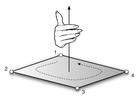
The present manual uses the "right hand coordinate system". In this system, the thumb of a palm-up, extended right hand corresponds to the x axis and the rest of the fingers to the y axis, with the z axis corresponding to the direction up from the exposed palm. (See figure, below.)
Concerning the direction of rotation of the axis, when the direction of movement of the axis seems to be towards oneself, this is called "counter-clockwise rotation" (CCW). If the thumb of one's right hand is the axis of rotation, then the direction of rotation towards which one's fingers are pointing will be counter-clockwise.
At this point, let us introduce the concept of homogeneous coordinates. The previous example expressing matrices showed the product and sum of matrices. It would be quite convenient if the second term "[l m n]" could also be expressed as the product of a matrix. Consider adding a dimension to a homogeneous coordinate system, expanding a 3x3 transformation matrix to a 4x4 matrix.
[x1 y1 z1 1] = [x0 y0 z0 1]
Taking P0 and P1 to stand for the position vectors [x0 y0 z0 1] and [x1 y1 z1 1] of points P0 and P1 and taking T to stand for the transformation matrix, then the following expression can be used to stand for the coordinate transformation.
P1 = P0T
By using homogeneous coordinates, all coordinate transformations, including scaling, translation, rotation, shearing, and projection, can be expressed in the form of matrix products.